Automating my swing gate
I have an old swing gate thats a pain to open/close especially during the monsoon
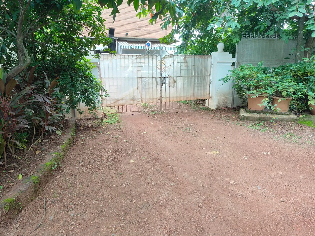
During the monsoon, the ground below it turns to mush and its especially difficult and annoying to open the gate while balanding the keys and an umbrella. So I’m going to automate it
I have no idea what im doing but hopefully it’ll all work out
Approach 1: convert It To A Sliding Gate?
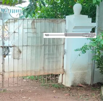
There are plenty of automation kits for a sliding gate but that would involve creating a rail thingy on which the wheels of the gate would rest. Something like this
We would also have to diplace it a bit to sit on the rails as opposed to the hinges so it could slide away. However, the ground probably wouldnt be able to handle the weight of the gate + cars driving over the rails and would sink…which would be bad
Approach 2: Keep It A Swing Gate
No real surprise as this is the only feasible option. The catch, however, is finding a kit that fits my gate as the mounting mechanism for most kits expect to be mounted right next to the gate with some offset. The topens blog has some amazing resources to figure out the best mounting position. In a perfect world, I would order a kit from them. However, I live in India and those kits are pretty pricey when combined with shipping + import duties
The Goal
I want to automate my swing gate while keeping the budget under USD 250
Caveats
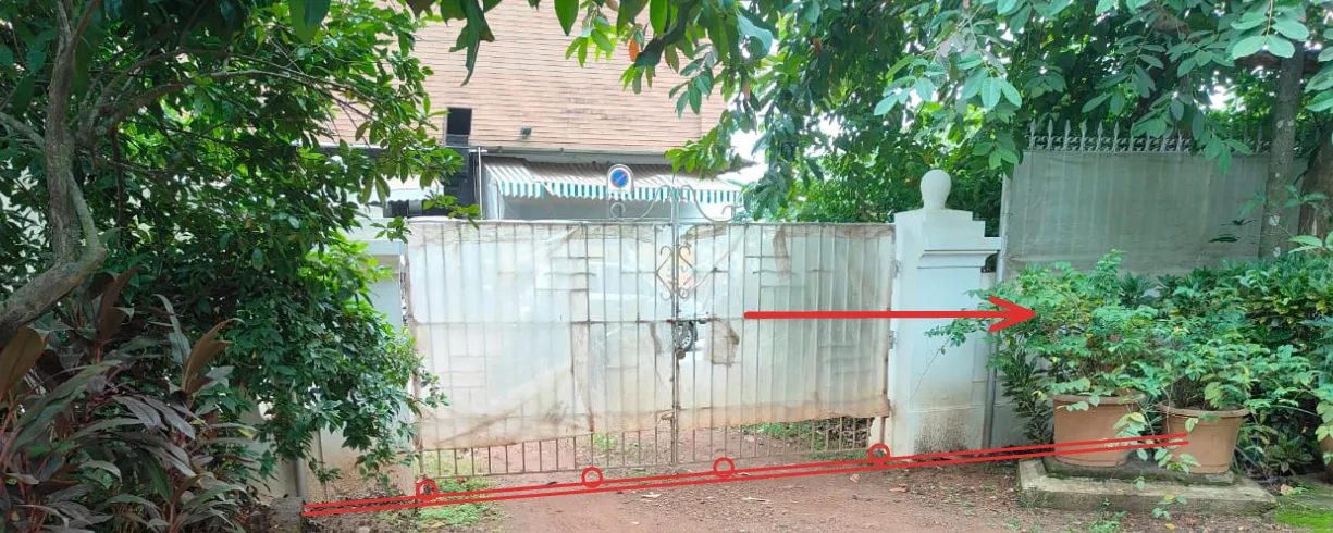
My mother does not want me to destroy her beautiful gate with my mechanical monstrosities. Instead, she wants me to mount it to the metal pipe near the gate
This makes things complicated but nothing a bored engineer can’t handle
The Parts Required
- A good linear actuator
- An arduino and a bunch of relays (minimum 4)
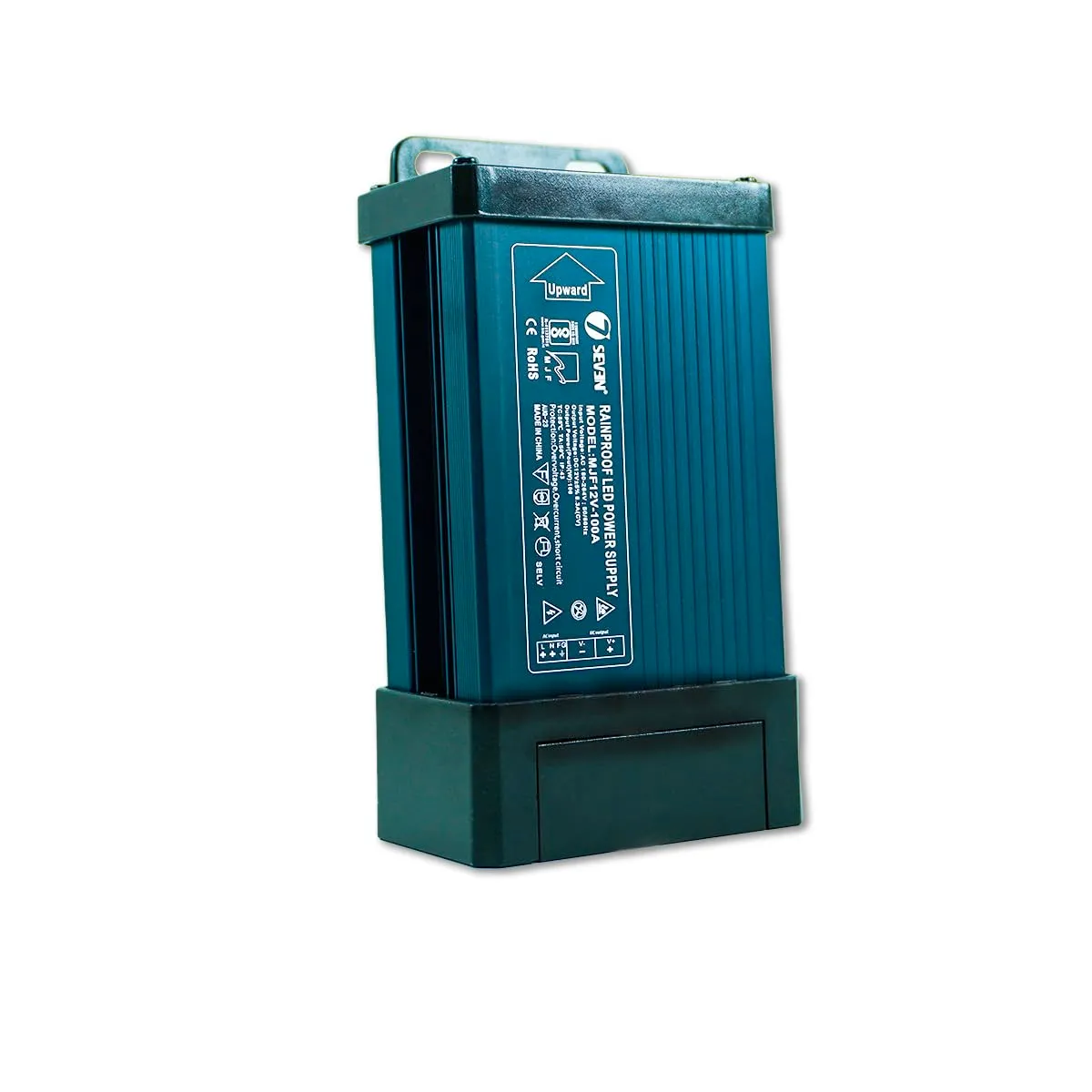
- An AC to 12V DC power supply thingy (check the minimum power draw of the actuator). I got this one from amazon.in https://www.amazon.in/dp/B0CTK84J74?ref=ppx_yo2ov_dt_b_fed_asin_title
The Theory Involved
A linear actuator looks like this inside
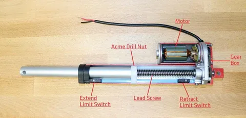 A motor turns some gears which turns a work gear which ultimately pushes a rod in and out of the housing. Every linear actuator will have a load rating which is the maximum force it can apply. You have to make sure your linear actuator has enough pulling/pushing force to account for friction, wind, weight of the gate and most importantly the actual force exerted based on your mounting
From the topens blog,
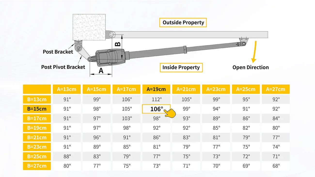
Using this diagram, lets science the crap out of this problem statement
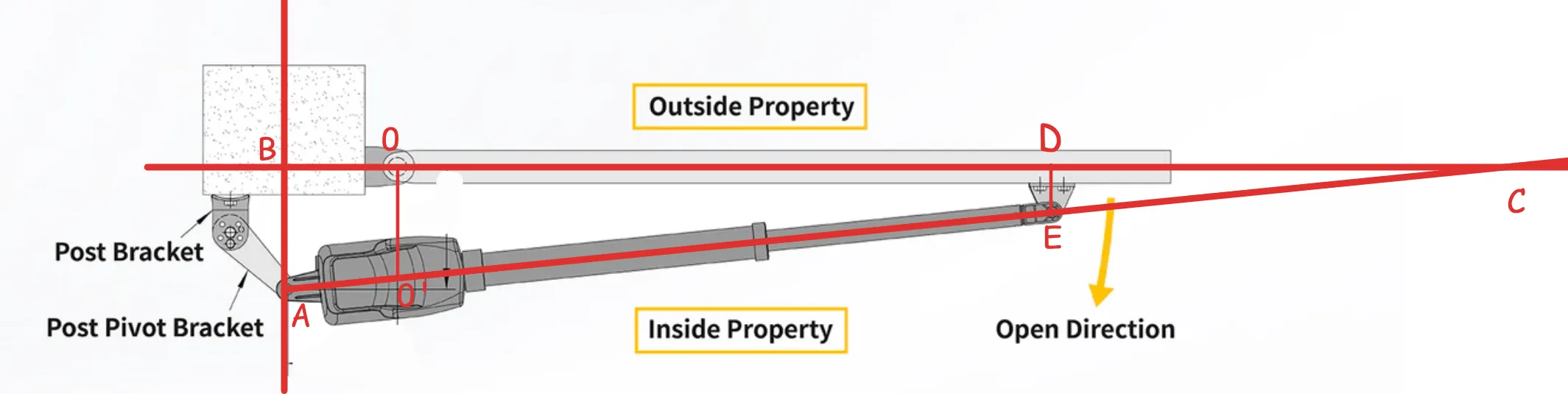
- is the gate hinge
- is the linear actuator hinge on which it can rotate
- is the point on the gate where the mounting brancket is
- is the point on the linear actuator arm where the mounting bracket is - generally the end of the arm (more on this later)
- is the point where line AB meets OD
- is the point where a line perpendicular to AB is drawn that cuts AE
- is the point where lines
BDandAEmeet once extended - is the weight of the gate (one half of the swing gate where g = 9.81 m/s^2)
- is the distance from the hinge of the gate to the center of gravity of the gate half (usually located in the center)
- is the friction coefficient - usually for iron on iron
- is the radius of the hinge (usually in cm)
Note: My math is kinda rusty and its been a while since i did anything like this
Now using , we can do this
Torque needed to turn the gate =
Torque needed to overcome friction =
So the minimum torque you need is:
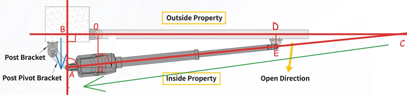
But we want only one component of the force - the blue arrow
So we can do =
So your actuator needs to have a minimum pulling force of
This is what my linear actuator says on the label
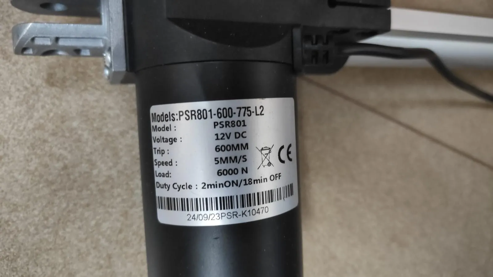
voltage = 12V DC (normal)
max extension length =
speed =
and finally, the duty cycle = ON and OFF. This is the real killer. A more powerful linear actuator will need a longer time . While there probably are linear actuators that are powerful with a shorter OFF duty cycle, they are pretty expensive. I got this one for Rs. 4.7k including shipping and GST (around USD 54)
If you look at the diagram above, you will see that the gate is closed when the linear actuator is fully extended - which means that, with some quick math of , opening the gate closing the gate will need to be followed by mins of rest, which is not what we want. Imagine opening a gate to drive your car in and then waiting 18 more minutes to then close the gate
One workaround is to mount the stuff in such a way that the linear actuaor is extended halfway (or even less) whhen the gate is closed. That will allow us to open and close the gate within one active duty cycle
WIP - this blog will be updated as progress is made