Automating my swing gate
I have an old swing gate thats a pain to open/close especially during the monsoon where the ground below it turns to mush and is annoying to open the gate while juggling between keys and an umbrella. So I’m going to automate it

I have no idea what im doing but I have a plan and hopefully it’ll all work out
Approach 1: convert It To A Sliding Gate?
There are plenty of automation kits for a sliding gate but that would involve creating a rail thingy on which the wheels of the gate would rest. Something like this

We would also have to diplace it a bit to sit on the rails as opposed to the hinges so it could slide away. However, the ground probably wouldnt be able to handle the weight of the gate + cars driving over the rails and would sink…which would be bad
Approach 2: Keep It A Swing Gate
No real surprise as this is the only feasible option. The catch, however, is finding a kit that fits my gate as the mounting mechanism for most kits expect to be mounted right next to the gate with some offset. The topens blog has some amazing resources to figure out the best mounting position. In a perfect world, I would order a kit from them. However, I live in India and those kits are pretty pricey when combined with shipping + import duties
The Goal
I want to automate my swing gate while keeping the budget under USD 250
Caveats
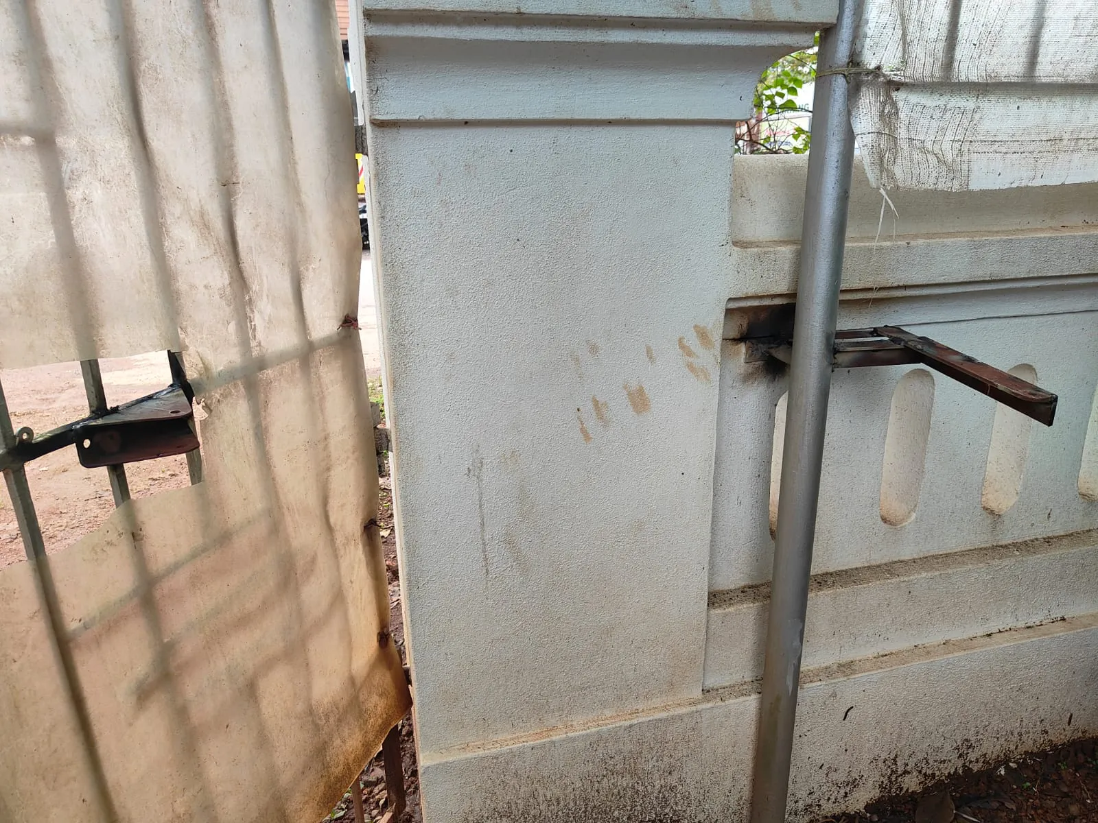
My mother does not want me to destroy her beautiful gate with my mechanical monstrosities. Instead, she wants me to mount it to the metal pipe near the gate

This makes things complicated but nothing a bored engineer can’t handle
Installation

The Parts Required
- A good linear actuator (with appropriate length both ways)
- An arduino (or a NodeMCU if you wanna use WiFi to control your stuff)
- A bunch of relays (minimum 4) or a LN98N motor driver (more on this later)
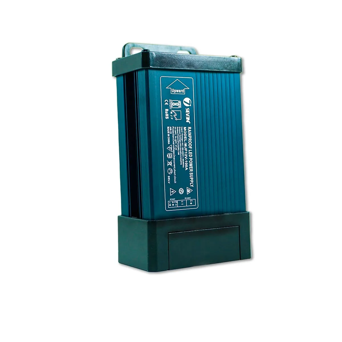
- An AC to 12V DC power supply thingy (check the minimum power draw of the actuator). I got this one from amazon.in
- A WiFi smart plug (optional, you can use physical switches if you want to)
The Theory Involved
A linear actuator looks like this inside
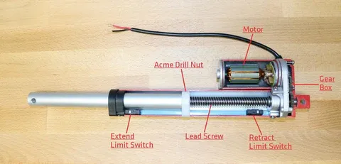 A motor turns some gears which turns a work gear which ultimately pushes a rod in and out of the housing. Every linear actuator will have a load rating which is the maximum force it can apply. You have to make sure your linear actuator has enough pulling/pushing force to account for friction, wind, weight of the gate and most importantly the actual force exerted based on your mounting
From the topens blog,
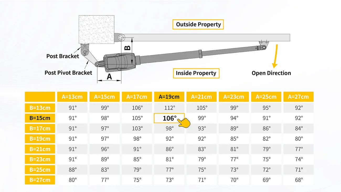
Using this diagram, lets science the crap out of this problem statement

- is the gate hinge
- is the linear actuator hinge on which it can rotate
- is the point on the gate where the mounting brancket is
- is the point on the linear actuator arm where the mounting bracket is - generally the end of the arm (more on this later)
- is the point where line AB meets OD
- is the point where a line perpendicular to AB is drawn that cuts AE
- is the point where lines
BDandAEmeet once extended - is the weight of the gate (one half of the swing gate where g = 9.81 m/s^2)
- is the distance from the hinge of the gate to the center of gravity of the gate half (usually located in the center)
- is the friction coefficient - usually for iron on iron
- is the radius of the hinge (usually in cm)
Note: My math is kinda rusty and its been a while since i did anything like this
Now using , we can do this

Torque needed to turn the gate =
Torque needed to overcome friction =
So the minimum torque you need is:
But we want only one component of the force - the blue arrow
So we can do =
So your actuator needs to have a minimum pulling force of
This is what my linear actuator says on the label

voltage = 12V DC (normal)
max extension length =
speed =
and finally, the duty cycle = ON and OFF. This is the real killer. A more powerful linear actuator will need a longer time . While there probably are linear actuators that are powerful with a shorter OFF duty cycle, they are pretty expensive. I got this one for Rs. 4.7k including shipping and GST (around USD 54)
If you look at the diagram above, you will see that the gate is closed when the linear actuator is fully extended - which means that, with some quick math of , opening the gate closing the gate will need to be followed by mins of rest, which is not what we want. Imagine opening a gate to drive your car in and then waiting 18 more minutes to then close the gate
One workaround is to mount the stuff in such a way that the linear actuaor is extended halfway (or even less) whhen the gate is closed. That will allow us to open and close the gate within one active duty cycle
The Wiring
We need the linear actuator to open and close and thus need to revese the direction that 12V DC flows from the power supply. The easiest way to do this is with something called an H bridge which is a bunch of switches in the shape of an such that s1, s4 and s2 and s3 are operated together
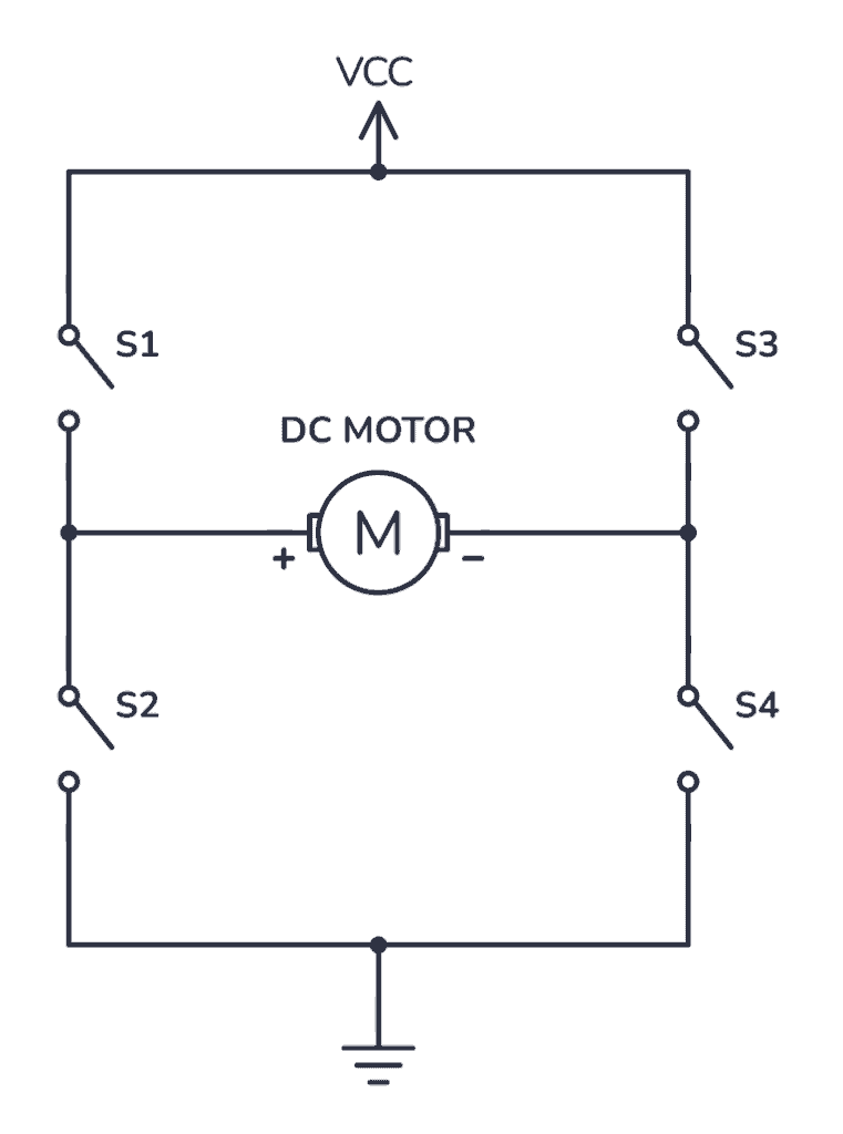
Image from build-electronic-circuits
You can technically do this yourself but its not worth the effort and the chances of you burning something down are high
As you can see, its a mess. The better approach would be to use a L298N motor driver which allows you to control both linear actuators individually with PWM (if you ever need it)
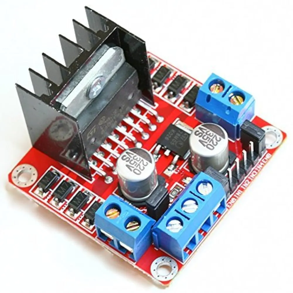
available on amazon.in
The working of a L298N motor driver is simple. This next part is important and you should read multiple sources before following along
-
Connect your power supply’s + to the input marked as 12V
-
Connect your power supply’s - to the input marked as GND
-
Keep the 5v jumper on if your supply is
12Vas that will allow theL298Nmotor driver to generate its own power from the input. I have read a few tutorials that you should keep it on if your input voltage is 12V and other tutorials asking you to remove the jumper and power its 5V input from the Arduino’s 5V (assuming you are using an Arduino). Your mileage may vary and you should be careful coz you can burn your motor driver
Signal guide for input pins
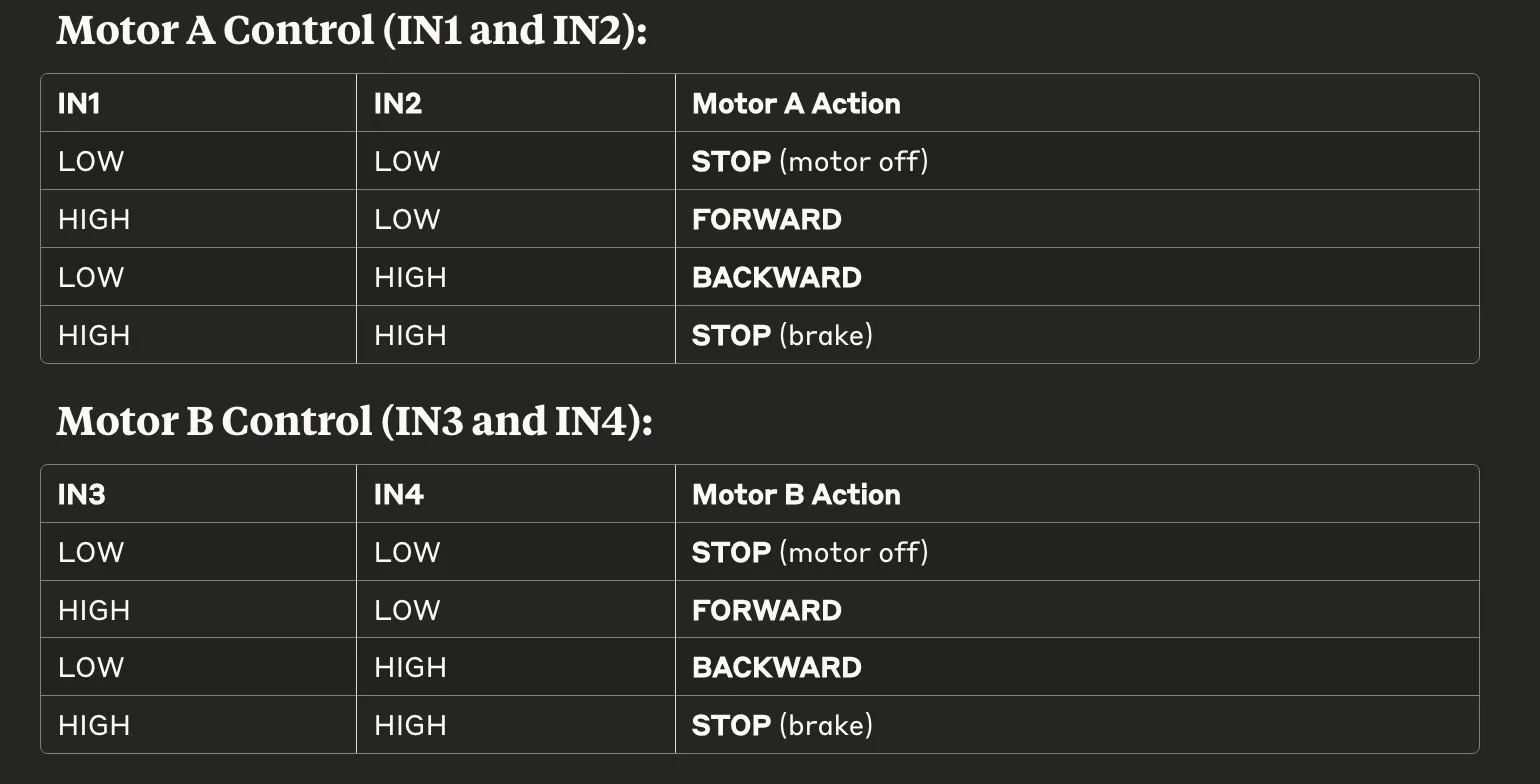 Neatly formatted from Claude ^
With that out of the way, lets plan how we want to open and close our gate. You can have a button or a switch but whatever the method, you need to be able to detect it using your microcontroller. I wanted to open and close my gate from phone coz thats the whole point - being able to have your gate open without getting out of your car. So I needed some sort of cloud service
Now I could write my own and host it somewhere but that would mean the server cannot go down and I dont want to spend that kind of money. Instead, I opted for a more unconventional approach
The hardware
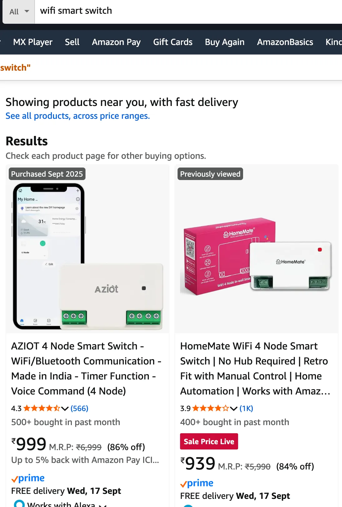
I got myself one of these
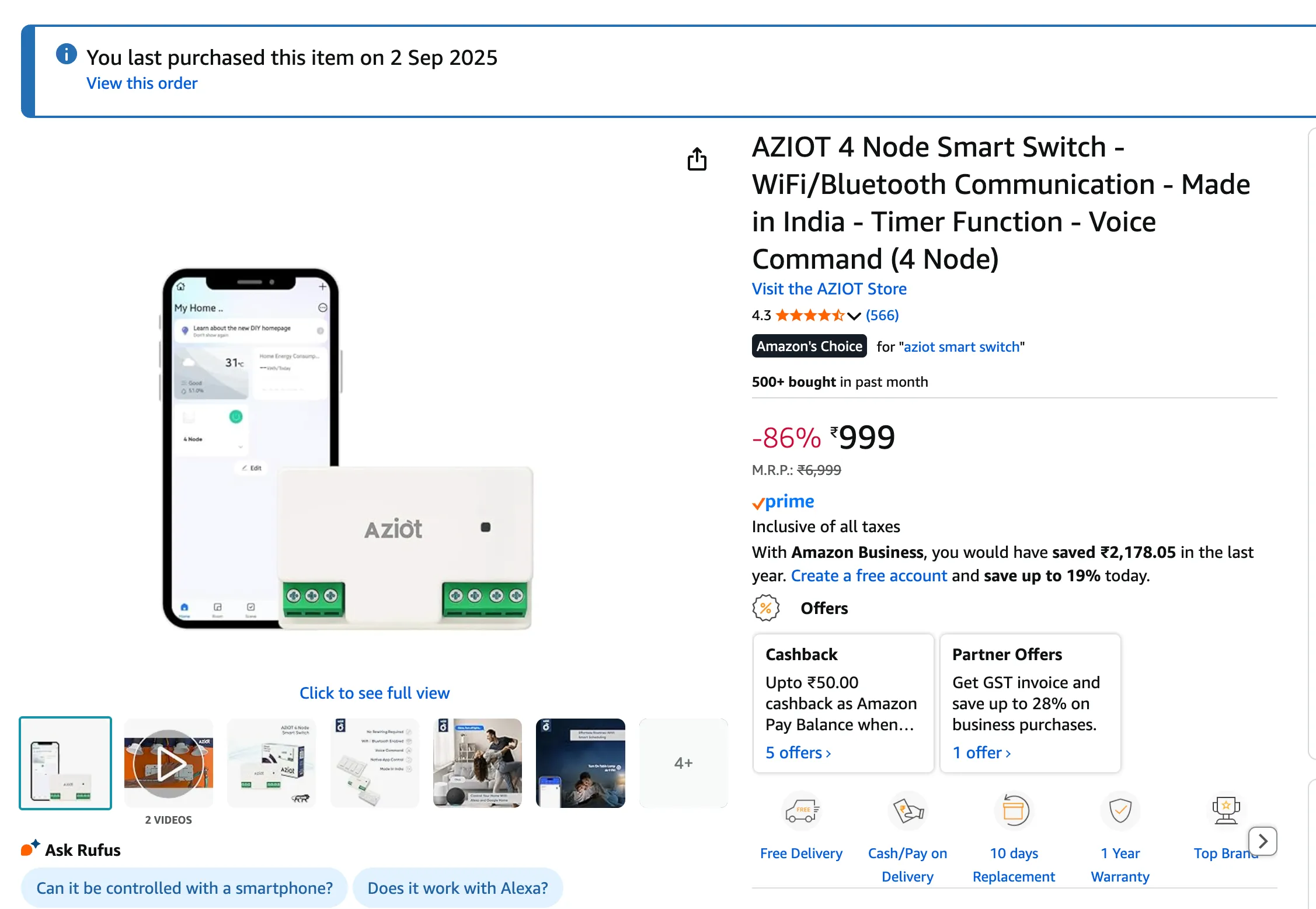
The company does not matter, the app and service do. If you zoom in on the picture, you will see it looks very similar to any other smart wifi thing sold in India or potentially the world. Thats because most of these smart devices use the Tuya platform to power their IoT stuff. Sometimes you can see stuff re-branded and sold under a different company
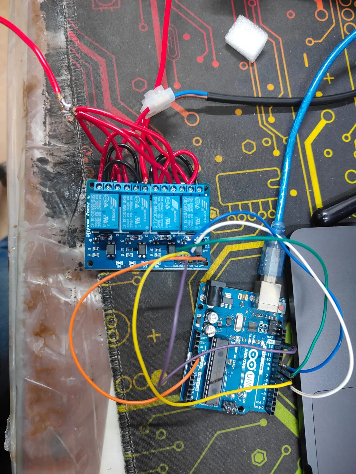
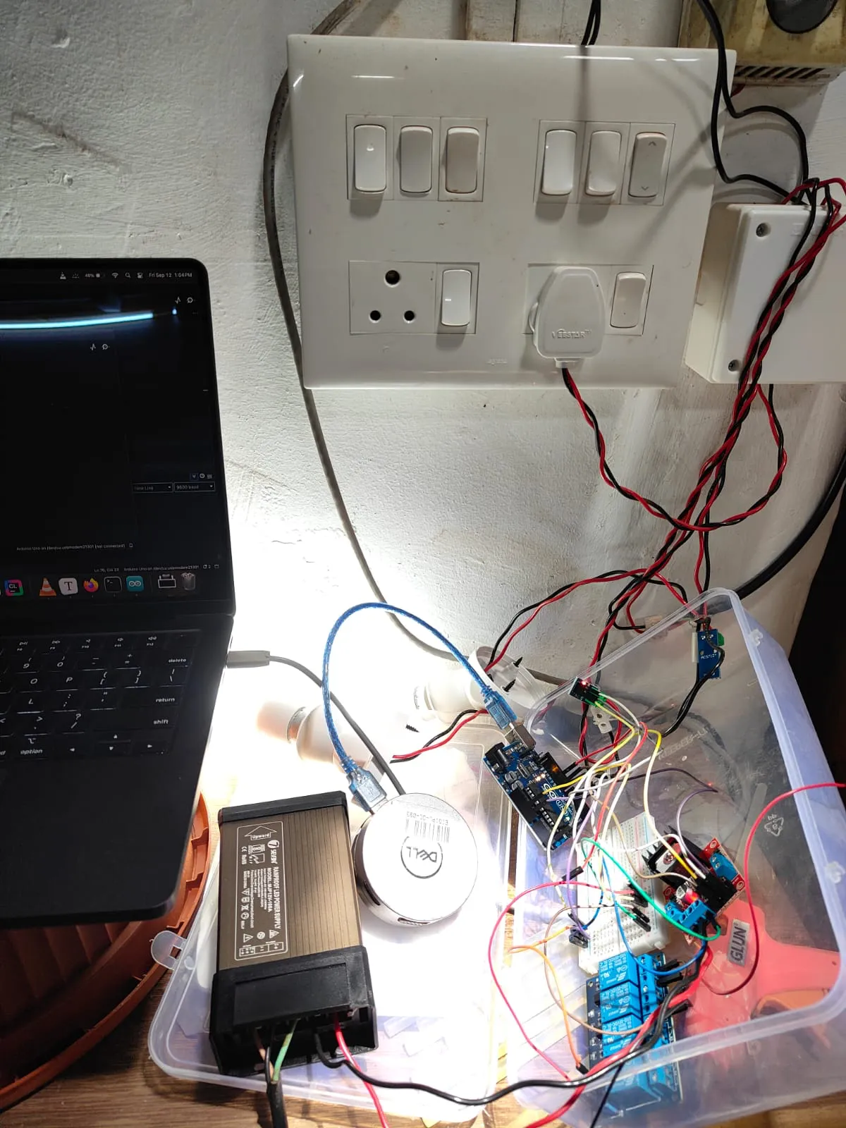
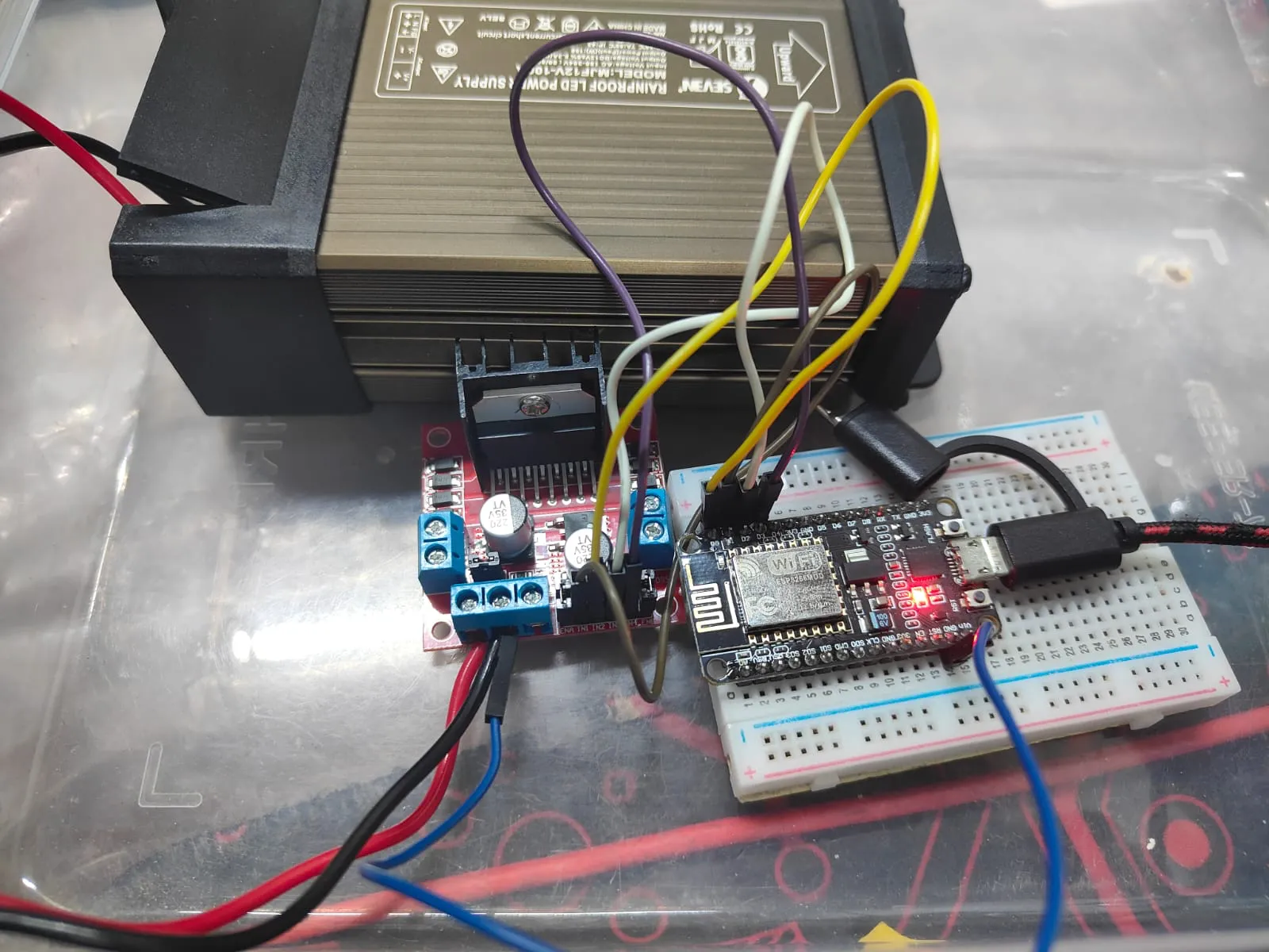
Sure there may be some differences but its all Tuya under the hood. Which is great coz I’m buying the cheapest one. Once installed, it will look something like this
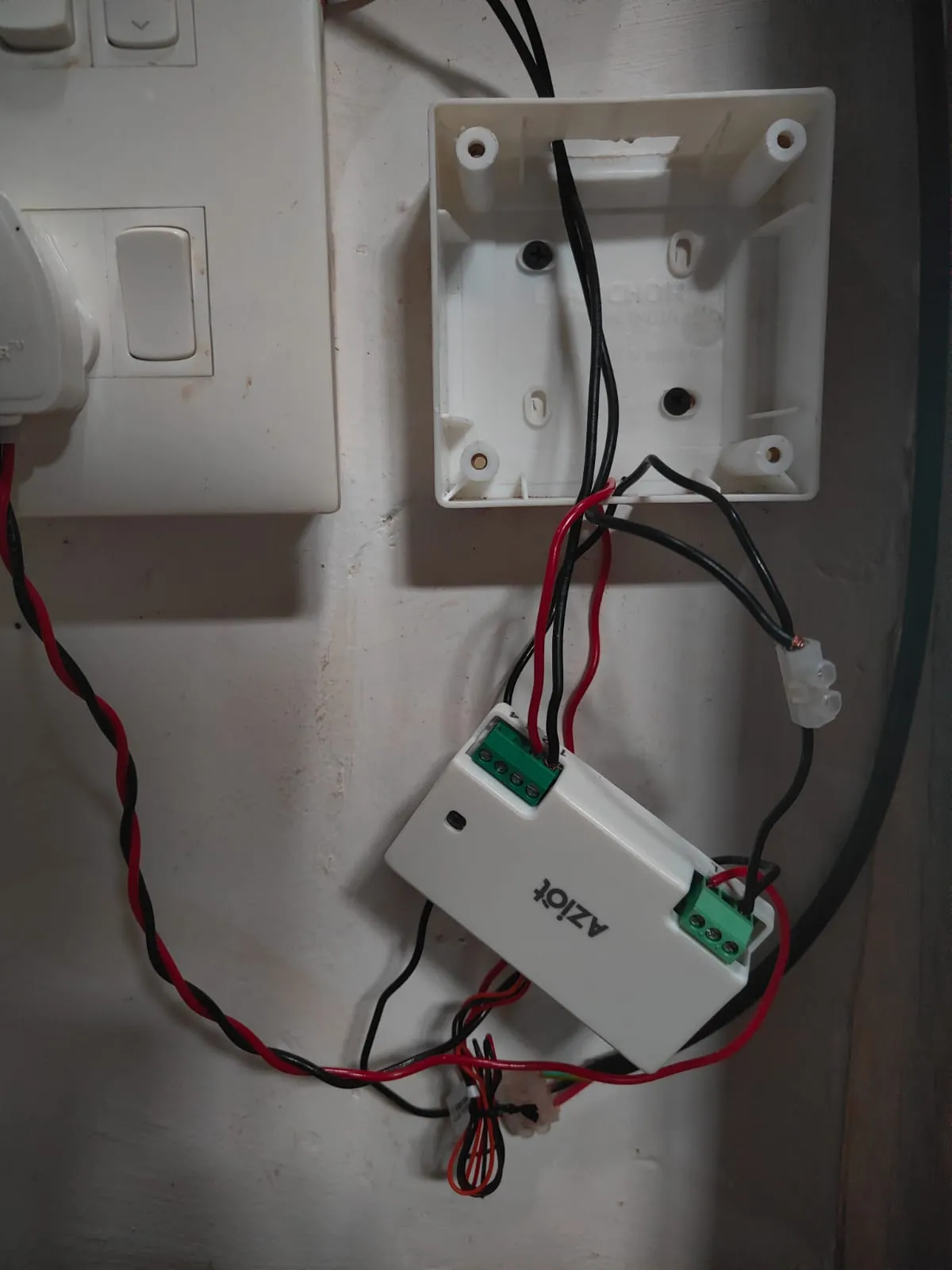
I know, my wiring is not great but this is temporary. I will be cleaning it up soon. Here’s the cool part though -
Because its all Tuya, you can literally use any app and not the one the company wants you to use. Lets download this very specific app that so happens to be the official Tuya app while everything else is just a re-skin of this. We’ll get to why we need this specific app in a while

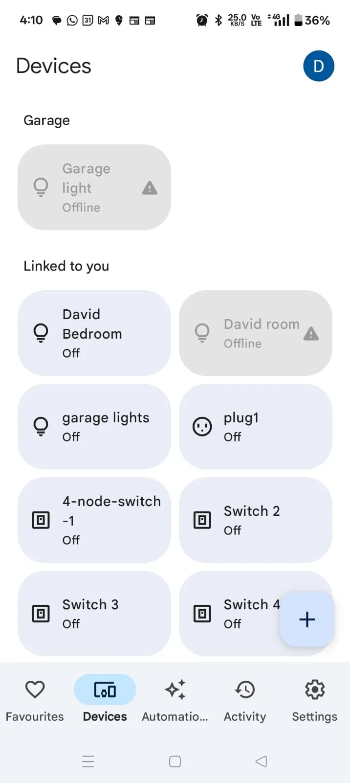
You dont have to create an account but you might as well. Use an email and some strong password and add your device to the account. Then you can sync your devices to your Google Home or Amazon Alexa services if you want. I would prefer Google Home coz of its cleaner UI. If you decide to sync your stuff to Google Home, you should see something like this
Problems
This is where the problems begin. However, I am writing this document after I have solved all of the problems and had to change my approach quite a bit, so things that dont work will seem obvious to you but I had no idea why stuff wasnt working
The problem - I need to do something that allows the Arduino (or NodeMCU) to detect when the switch is ON or OFF so it can OPEN or CLOSE the gate respectively
I had planned to have each side of my gate controllable so I would allot 2 switches to turn ON and OFF to signal the gate opening and closing respectively. However, the smart switch dealt with 240V AC while my Arduino (now NodeMCU) dealt in 5V DC.
Approach 1 - a 5V phone charger
My first approach was to use 5V phone chargers to connect to the Arduino to detect when they (and consequently the switch) are ON or OFF. This seemed like a good idea coz i wouldnt be doing much wiring of mains and I can use an extension cable or something to connect the chargers into
I got an old USB cable that was thankfully power only and cut the end off to see 2 cables - a RED and a BLACK cable
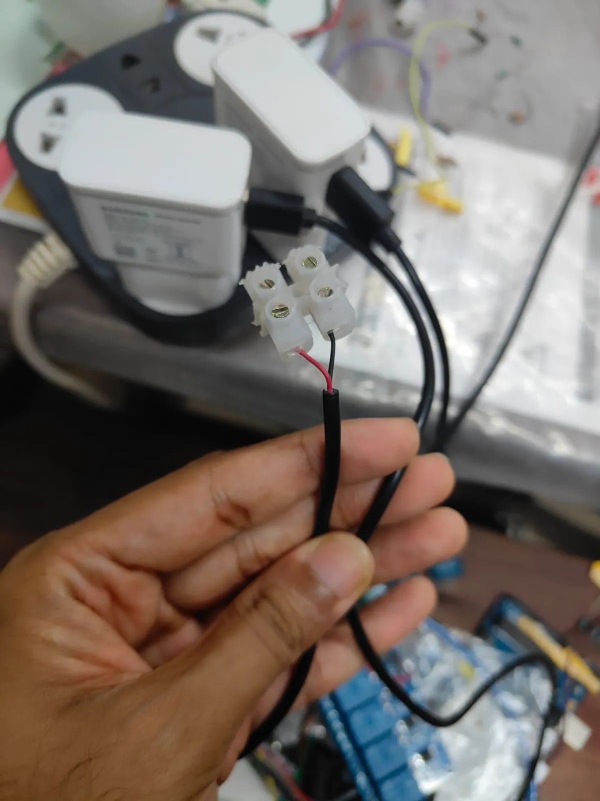
Since the phone charger was old, I measured the voltage with my multimeter and it turned out to be 5.02 V. However, while this should be within the Arduino’s input range, I didnt trust the charger to handle spikes well. Therefore I opted to use a voltage divider of two equal resistors and measure the voltage after the first one. As I’m using two resistors of the same resistance, the voltage drops equally across the two - i.e., i should get 2.5V when the charger is ON and 0V when the charger is OFF
At least thats what I thought. Now, my knowledge of electronic stuff is at best a hobbyist and I dont know the exact terms for stuff. But here is what I found from searching for it online with some extrapolations - the issue is most phone chargers have capacitors that hold charge even when the power is turned off. Normally this isnt an issue but since my voltage divider was made of very high resistance resistors, the current draw was so small that it took around a minute for the capacitors to discharge and the voltage to drop to 0. That means the time between you pressing the GATE CLOSE button and the gate actually closing is around 1 minute. Which… isnt that great
Even when i added a bleed resistor of lower resistance, it didnt make much of a difference. Note that most of stuff came from old Arduino kits so I had to make do with what i had
Approach 2 - current sensor
Capacitors are annoying, lets get rid of them. Instead of relying on phone chargers, I can turn on an AC light and use a current sensor to detect the voltage and figure out a threshold above which it would be ON. Simple enough right? Yeah thats what I thought too
I bought a few of these ACS712 Hall Effect current sensors
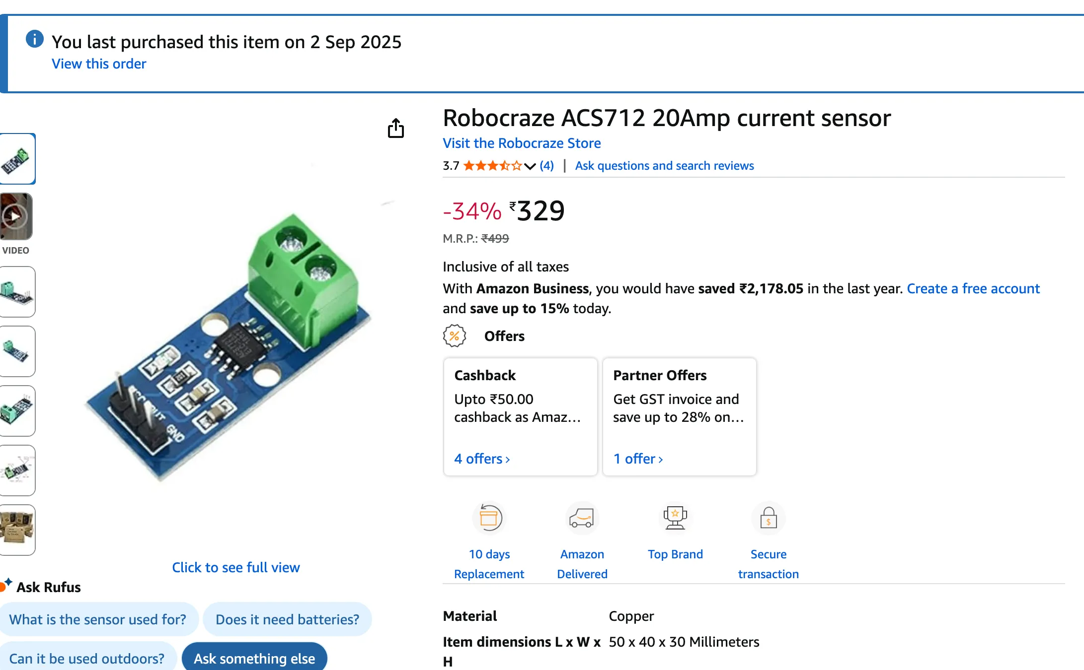
I wired it up such that the switches would turn on AC light bulbs and then I would use the current sensor to figure out if the current draw was above a threshold or not
And that seemed to work…sometimes. There was one major issue with this approach - I bought the 20A current sensors. Why? Coz I’m an idiot and didnt do my research well
Whats the big deal you might be asking? Well, the higher the current rating of the sensor, the less accurate it is with smaller currents. And my AC lights had a power rating of 4W which on 240V had an approximate current draw of 0.0167 A or 16.7 mA which is waaay below the 100 mV/A rating of the 20A sensor
The ACS712 sensor works on the principles of Hall Effect - it measues the magnetic field generated by the input current and figures out what the current is with some math. While yes, a magnetic field is generated with 16.7mA, the 20A sensor is unable to measure it accurately due to the threshold (100mV/A) being much higher than the actual current. This is important because AC current is a sine wave so you cannot directly “measure” the stuff using analogRead() as you’ll be getting the value of the voltage sine wave at that point in time. Instead you have to collect a bunch of samples and get the RMS value and then do some more math to get your final answer. As mentioned before, as the 20A sensor has a higher threshold than the current inputted, it cannot accurately and reliably detect the current as what you might think may be current might just be noise
So yeah, thats the wrong sensor for the job. Watch this video to learn more about what to do and what not to do, including what sensors to get to measure small AC currents
TLDR - you need a CT sensor if you want to measure AC current
Tutorial: https://docs.openenergymonitor.org/electricity-monitoring/ct-sensors/interface-with-arduino.html
Approach 3 - Software Switching
If Google Home can talk to Tuya, surely I can too. Turns out Tuya does indeed have an API and stuff you can use but there are a few caveats -
- Your devices must be registered the the official Tuya Smart Life app as mentioned before. While some sources online say you can use a re-skinned app, it didnt work for me
- You need to create an account on https://platform.tuya.com/ and setup a new project and link your devices to that project
- You cannot access the state directly (unless you use the free trial which expires in a month). Well you can but its a binary protocol and not somehting you can
curl. We will install Home Assistant with the tuya integration
Watch this video to figure out what to do
Or TLDW
-
Create an account
-
Open the smart life app and from the bottom bar, select “Me”, then select the settings icon on the top right corner > Account and Security > Region and see what it says. For me its “India”. This is important for later
-
Select the Data Center of your project to match the region of your app and press the blue “Create” button
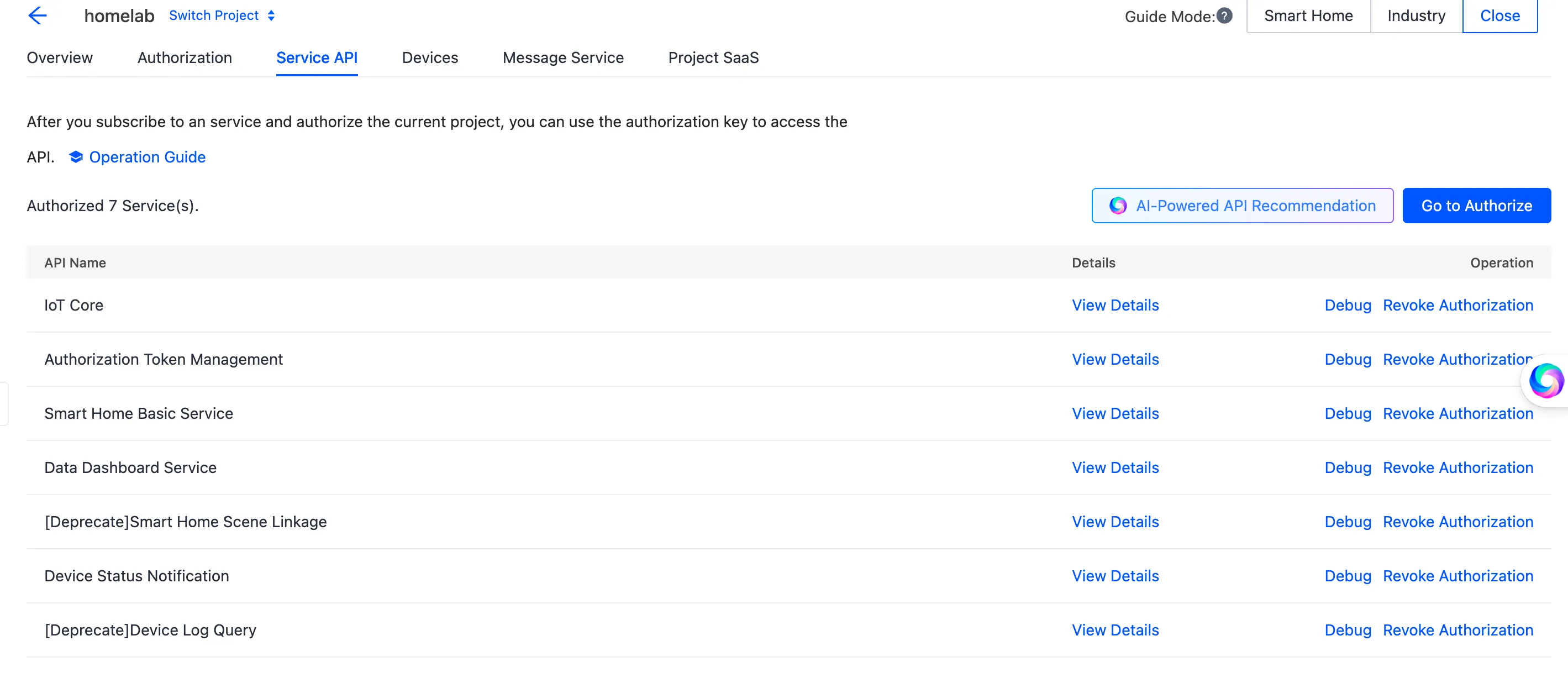
-
Make sure you move the “[Deprecated] Device Log Query” to the Selected API Services. If you forgot to add this, you can always add it later. These are the services I have
-
If you need to active a free trial to select the “IoT Core”, please do so. Your usage will, in most cases, be well within the free trial limits
-
Now open the “Devices” menu and press the big blue “Add App Account” button
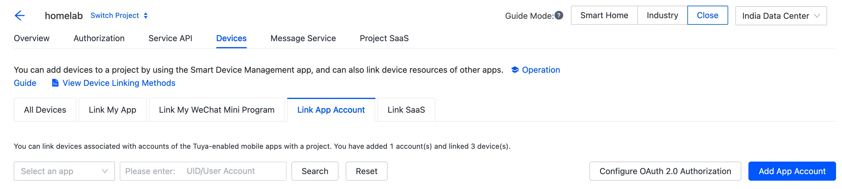
-
Upon clicking it, you will get a QR code that you have to scan with the official Tuya Smart Life app. The specific QR Code Scanner can be found on the “Me” page next to the settings icon. This scanner is different from the scanner used to add new devices. Scan the QR code and follow the authentication prompts. Once done, you should see your devices in the list
-
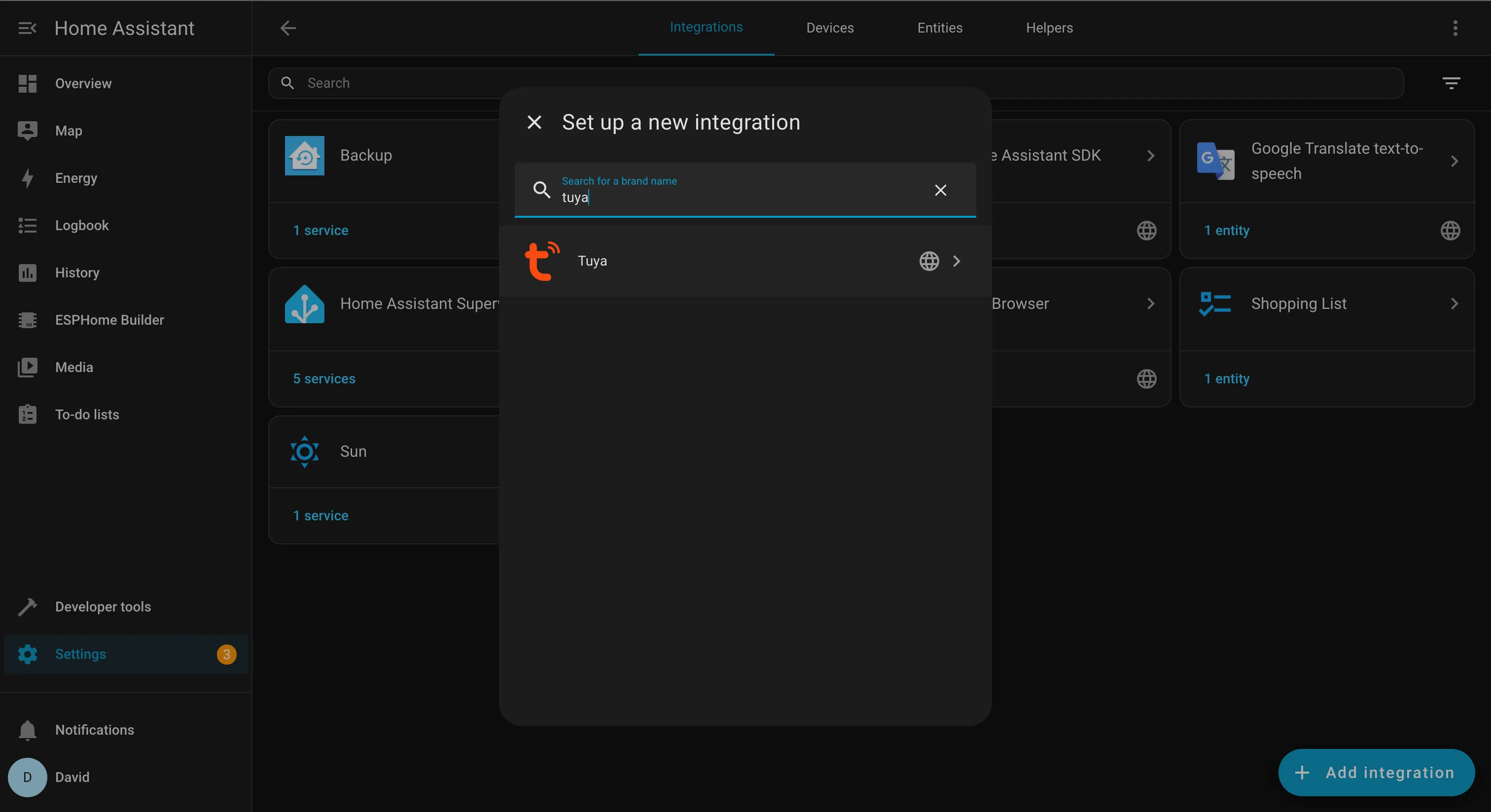
Now we go back to Home Assistant and add the “Tuya” integration
 Follow the instructions to link stuff. Your User Code is found on the Me > Settings > Account and Security page . You will have to scroll down a bit on that page
 -
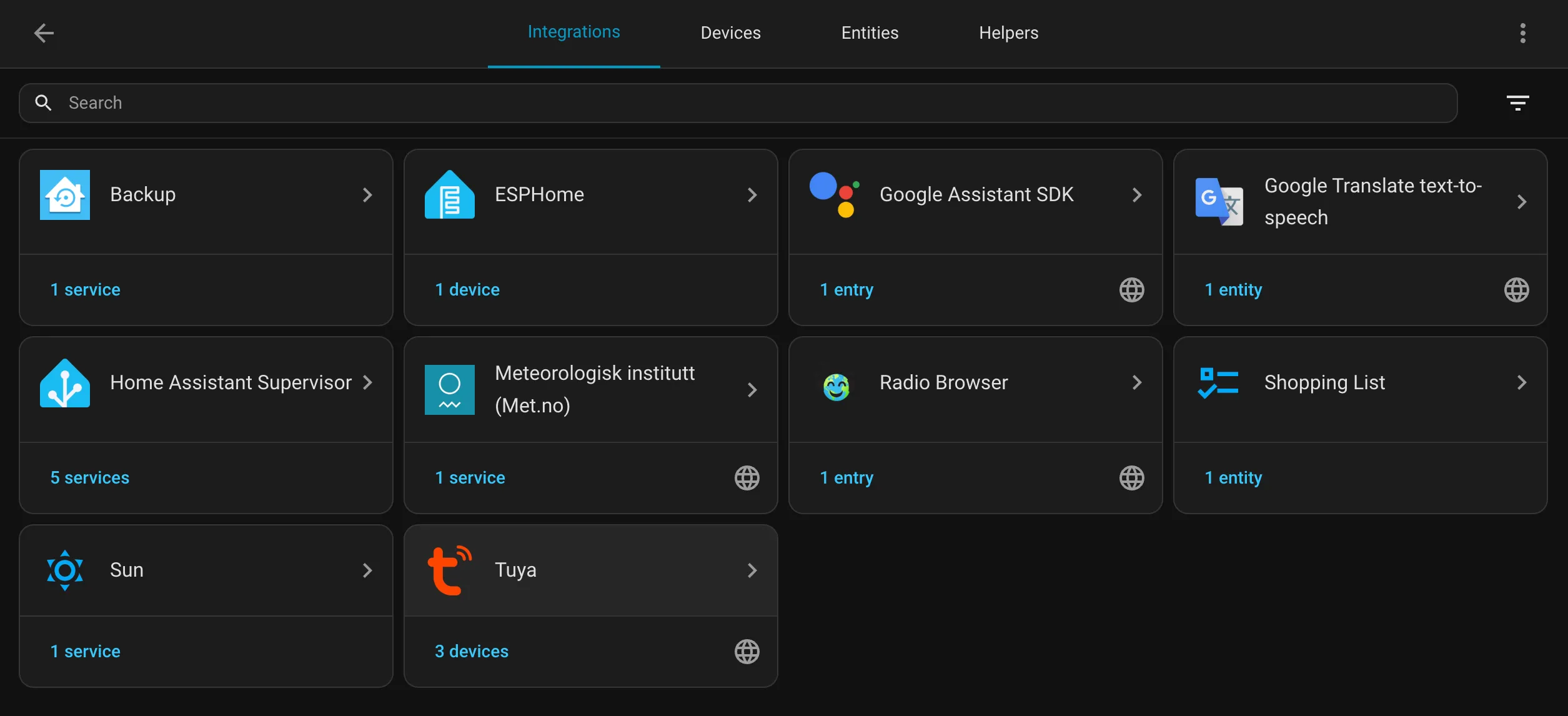
Once done, you should see a Tuya card
 Click it and you will see a list of devices. Click on the arrow to expand the smart switch and you will see something like this
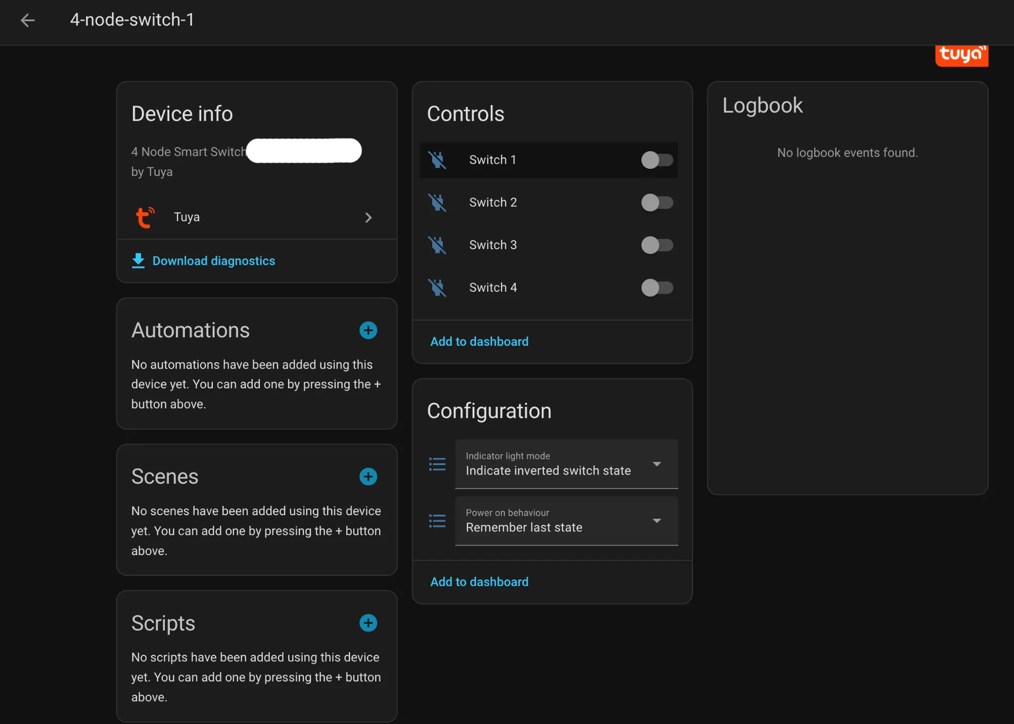
Click on the “Switch 1” or whatever you have named it and from the modal that pops up, click on the Settings icon
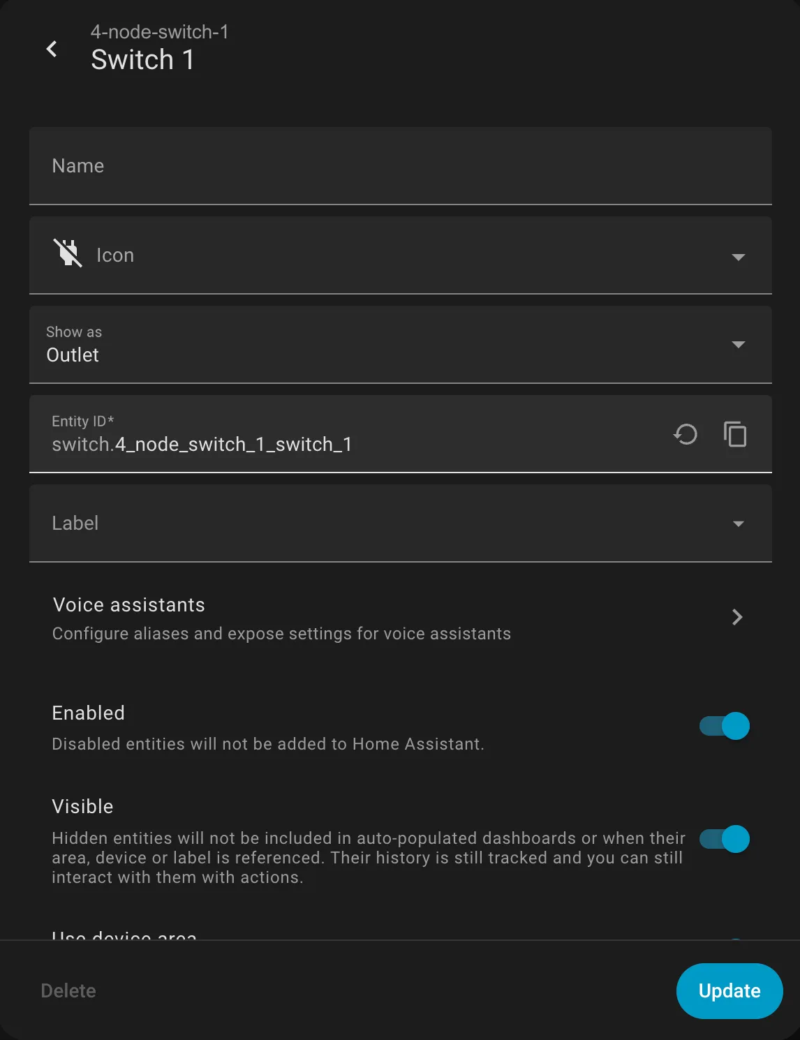
The
Entity IDfield is what you want -
With the
Entity IDobtained, you will need an auth token from home assistant. From the left menu, click on your username and then the settings tab and scroll down. Follow the instructions to generate the token -
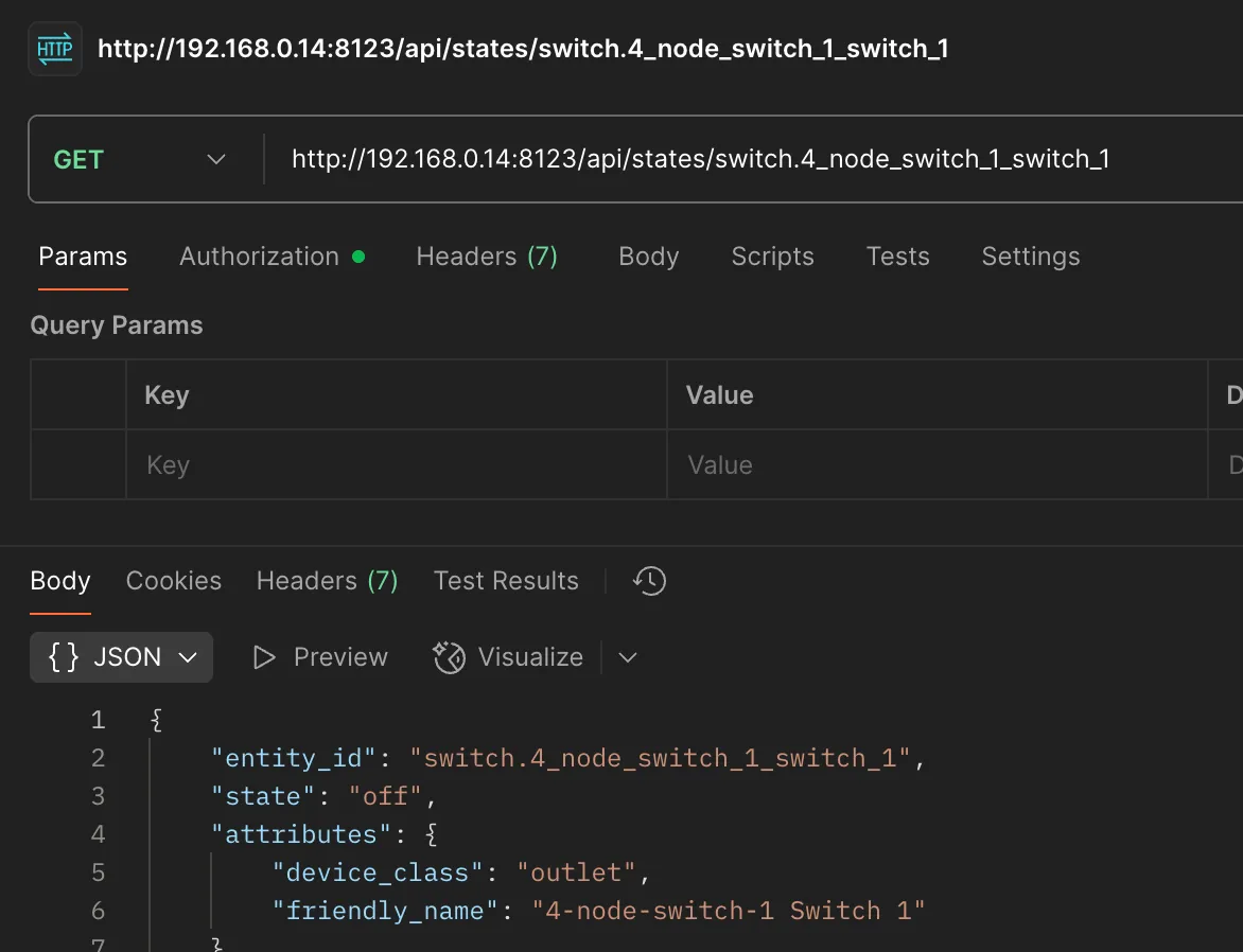
Using the
Entity IDand the token, use this CURL to get the state of your thing
curl --location 'http://192.168.0.14:8123/api/states/switch.4_node_switch_1_switch_1' \
--header 'Authorization: Bearer YOUR_TOKEN_HERE
New Wiring
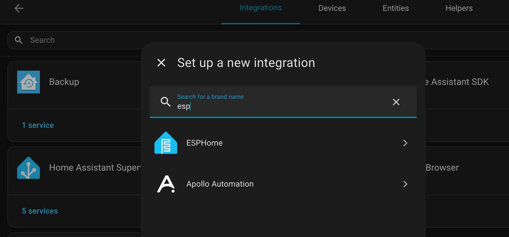
Since we are already using Home Assistant to get the state of the light switch, we might as well use it to make our lives easier. Lets install the “ESPHome” integration
Note - If you are running Home Assistant as a container, you might face issues with this integration. You might also want to increase the CPU and RAM limit
ESP Home has some really cool features - Over The Air (OTA) updates of code, web servers to control your arduino stuff and everything is yaml. However, you will need to flash your NodeMCU with a custom ESPHome firmware. You can generate this from the ESPHome integration you just installed. You can then flash it to your NodeMCU. However, chrome needs Home Assistant to be served on HTTPS to access the NodeMCU via WebSerial and chances are that your Home Assistant is using HTTP
Therefore, you can download the .bin file from Home Assistant and flash it to your NodeMCU from https://web.esphome.io/?dashboard_wizard and see it in your ESPHome dasboard

Give it a few minutes and it’ll pop online

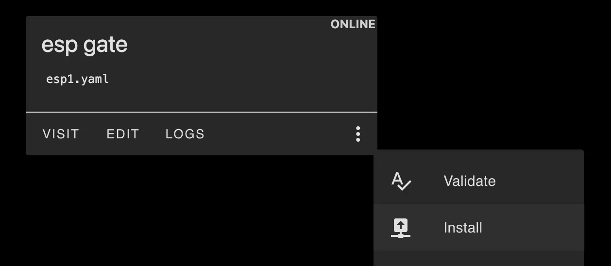
Press the “EDIT” button and edit the YAML and add your stuff. Using the L298N input pin guide previously mentioned,
esphome:
  name: esp1
  friendly_name: esp gate
  on_boot:
    priority: 600
    then:
      - lambda: |-
          if (id(gate_state).state) {
            ESP_LOGI("custom", "YES");
            // ON: D0 = HIGH, D1 = LOW
            id(d0_output).turn_on();
            id(d1_output).turn_off();
            id(d2_output).turn_on();
            id(d3_output).turn_off();
          } else {
            ESP_LOGI("custom", "NO");
            // OFF: D0 = LOW, D1 = HIGH
            id(d0_output).turn_off();
            id(d1_output).turn_on();

            id(d2_output).turn_off();
            id(d3_output).turn_on();
          }
...


output:
  - platform: gpio
    id: d0_output
    pin: 16
  - platform: gpio
    id: d1_output
    pin: 5
  - platform: gpio
    id: d2_output
    pin: 4
  - platform: gpio
    id: d3_output
    pin: 0

binary_sensor:
  - platform: homeassistant
    id: gate_state
    entity_id: switch.4_node_switch_1_switch_3
    internal: true
    on_state:
      then:
        - lambda: |-
            if (id(gate_state).state) {
              ESP_LOGI("custom", "YES");
              // ON: D0 = HIGH, D1 = LOW
              id(d0_output).turn_on();
              id(d1_output).turn_off();
              id(d2_output).turn_on();
              id(d3_output).turn_off();
            } else {
              ESP_LOGI("custom", "NO");
              // OFF: D0 = LOW, D1 = HIGH
              id(d0_output).turn_off();
              id(d1_output).turn_on();

              id(d2_output).turn_off();
              id(d3_output).turn_on();
            }
Where: IN1 of the L298N is connected to pin D1 of the NodeMCU IN2 of the L298N is connected to pin D0 of the NodeMCU IN3 of the L298N is connected to pin D3 of the NodeMCU IN4 of the L298N is connected to pin D4 of the NodeMCU
GND of the L298N is connected to the GND of the NodeMCU and -ve of the Power Supply
Once done, Save the YAML and press the 3 dots > Install > Wireless
Once done, you can see the logs when you turn that switch on/off
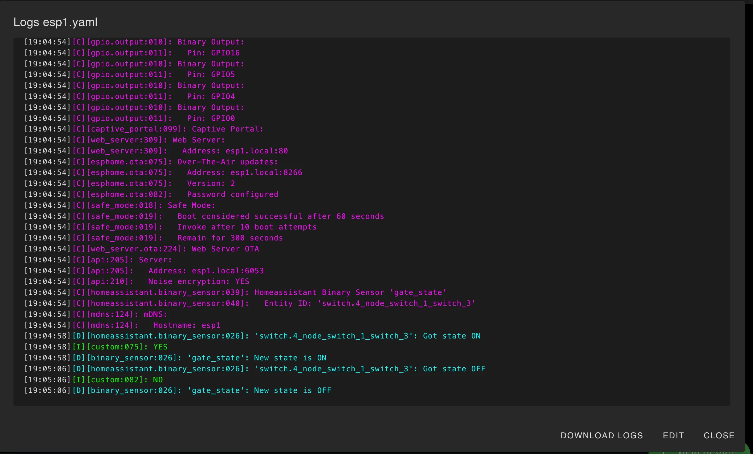
https://drive.google.com/file/d/1gma1VvU9N3NxiYGCTzDKQP9hqK_9ywgn/view?usp=sharing
Future Plans?
You may or may not have noticed something interesting - the blue “Add Device” button
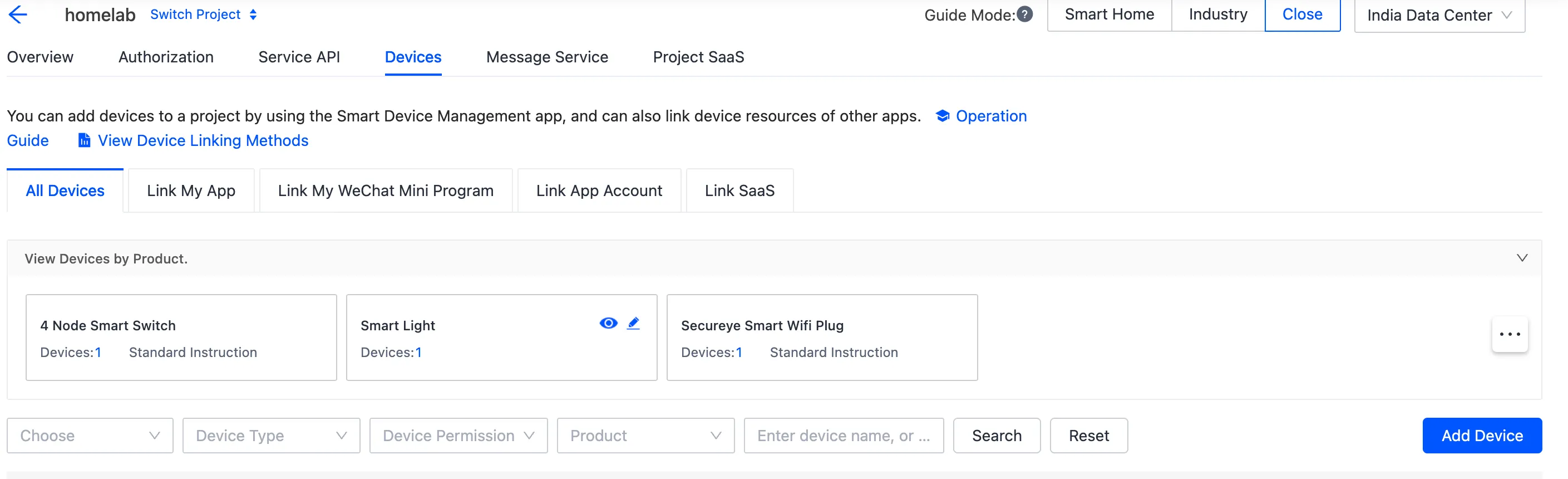
You can probably guess what this does - you can create a virtual device that you toggle on/off. If thats all you use a smart switch for, this is the endgame
This document is a WIP and will be constantly updated. Last update: 15 September 2025